Sunday, March 10, 2024

Convolutional Neural Networks


An introduction to Convolutional Neural Networks


Introduction: What is an artificial neural network?

In recent times, words like deep learning, machine learning and artificial intelligence have become so common that even school kids are now somewhat familiar with these terms. The advent of Machine Learning has been followed by the rise of Artificial Neural Networks (ANNs). ANNs are computational processing systems used to handle a large amount of data. They take inspiration from the way biological nervous systems operate. These neural networks have a number of hidden layers stacked upon each other. The basic computational units of a neural network are called neurons. Just like neurons in the human brain, these fundamental blocks take in input signals, process them and produce the output. Figure 1 below shows the basic structure of any ANN architecture:
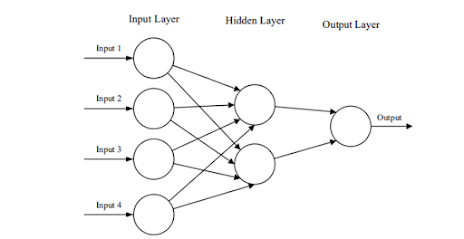

Figure 1

What are convolutional neural networks?

In this article, we will focus on Convolutional Neural Networks (CNNs). CNNs are similar to ANNs, but they are used to perform tasks such as image processing and pattern recognition within images. An image is nothing but a two dimensional signal that can be represented in the form of a matrix. While setting up the CNN architecture, one must take into consideration the fact that the input to such systems consists of images.


Methodology:

A CNN comprises three important layers which can be stacked together to form the CNN architecture. These are convolutional layers, pooling layers and fully connected layers.


1.  Convolutional layer

This layer is based on the linear mathematical operation of convolution in which two signals are multiplied to produce a third signal. When data hits this layer, convolution takes place between the input and a filter of particular size. The output of this layer is in the form of a 2D activation map which gives information about the image itself.

2.  Pooling layer

The convolutional layer is followed by a pooling layer. The primary aim of this layer is to reduce the computational complexity of the model and to make it more cost effective. Thus the pooling layer is destructive in nature and reduces the dimensionality of the representation.

3.  Fully connected layer

The fully connected layer consists of neurons that are connected directly to the neurons of the two adjacent layers. In the previous layers, the input image is flattened and fed to the fully connected layer. In this layer, mathematical functions operate and classification of the image takes place. 


Figure 2 below shows the structure of the layers of a CNN which have been described above.


Figure 2


Observation:

Despite the fact that CNNs require a relatively small number of layers,there is no set way for formulating a CNN architecture. The common architecture includes stacking of convolutional layers, followed by pooling and fully connected layers. Another practice is to stack multiple convolutional layers before the pooling layer so as to handle more complex features. Also to reduce the computational complexity, large convolutional layers are split into smaller ones. CNNs are very powerful machine learning algorithms but can be resource heavy too. Hence to address this problem, the spatial dimensionality of the input images is reduced.


Conclusion:

Thus to conclude, we can say that convolutional neural networks focus on only a specific type of input and hence, it is easier to set up the architecture for the same. Applications of CNNs include research in the field of image analysis which range from image and video analysis, medical image processing, image classification and computer vision.


References:

1.  https://www.researchgate.net/publication/285164623_An_Introduction_to_Convolutional_Neural_Networks

2.  https://www.upgrad.com/blog/basic-cnn-architecture/

Written by,

Mugdha Deshpande

SY EnTC


Saturday, April 29, 2023

Effect of Preheating and Exhaust Gas Recirculation on Diesel Engine

 Introduction:

The depletion of fossil fuel resources has emphasized the need for alternative sources of energy and to improve the performance, combustion, and emission characteristics of existing internal combustion engines. Exhaust flue gas loss is the major loss that affects the performance of the engine. Researchers have used techniques such as exhaust gas recirculation (EGR) to reduce NOx emissions. Hountals et.al (2008) verified the effect of using cooled EGR gas temperature on turbocharged DI heavy-duty diesel engines. Different technologies such as thermoelectric generation, bottoming Rankine cycle, and six-stroke cycle have been explored for potential energy savings and improvement in performance.

Researchers have been trying to improve the thermal efficiency of diesel engines by applying different techniques. Thakar et al (2018) designed a counter flow shell and tube heat exchanger, Tilmann Abbe Horst et al (2013) developed a dynamic model of heat exchanger for exhaust gas recovery, Saiful Bari & Shekh Hossain (2013) experimented with two heat exchangers to estimate exhaust heat recovery, Hui Xie & Can Yang (2013) studied heavy-duty diesel engines for waste heat recovery using Rankine Cycle System (RCS) model, Love et al (2012) tested thermoelectric devices on a test bench to improve performance of waste heat recovery systems.


Experimental Analysis:

The experimentation was conducted on a 3.5 kw capacity 4-stroke single-cylinder stationary diesel engine with a counter flow shell and tube heat exchanger. Six configurations were tested: Diesel without Heat Exchanger (WHE), Diesel without Heat Exchanger (WHE) and 6% EGR, Diesel with Heat Exchanger (HE), Diesel with Heat Exchanger (WHE) and 12% EGR, and Diesel with Heat Exchanger (WHE) and 12% EGR. The data acquisition device was NI USB-6210, 16-bit, 250kS/s.


Results:


The variations of the various performance parameters of the engine with respect to load are given below:

1. Brake thermal efficiency-

Brake thermal efficiency was decreased with diesel heat exchanger, 2.94% at part load and 18% at full load, and decreased with heat exchanger and 12% EGR.


2. Volumetric Efficieny-

The volumetric efficiency of a diesel engine with a heat exchanger and exhaust gas recirculation varies with load, with decreased efficiency with a heat exchanger and 6% EGR at 75% load and almost unchanged at all loads.


3. Brake specific fuel consumption-

Brake specific fuel consumption is decreased with an increase in load for base gasoline and with a decrease in fuel consumption for diesel with a heat exchanger. This is due to the increased BSFC value of air in the heat exchanger, which improves the combustion in the cylinder. It is observed that the same fuel consumption remains the same for both diesel and heat exchangers, with 6% EGR (Energy Return on Investment) at 50% load.


4. NOX emissions-

NOx emission increases with increasing oxygen content and injection timing, due to higher temperatures and advanced injection timings. NEGR and optimization of injection timing can help avoid fixation of oxides of nitrogen, reducing the temperature of the charge.


Conclusion:

The experiment can be concluded by saying that heat exchangers are used to heat inlet air, but their efficiency is lower than diesel. Base diesel has a higher brake thermal efficiency than other configurations, while volumetric efficiency is decreased due to the heating of air.


Reference:

Experimental Investigation of Effect of Preheating of Air and Exhaust Gas Recirculation on Four Stroke Diesel Engine - IOPscience


Credits:

Bhakti Gujarathi

SY Manufacturing


Saturday, March 18, 2023

Use of Catalyst in Pyrolysis of Polypropylene Waste into Liquid Fuel

 Introduction:

Polypropylene (PP) is a widely used thermoplastic material that is found in a variety of products such as packaging materials, automotive parts, and household items. While PP has many advantages, such as its low cost and high durability, it also poses a significant waste management challenge. PP waste often ends up in landfills, where it takes hundreds of years to degrade or is incinerated, which releases harmful emissions into the atmosphere. To mitigate these environmental concerns, researchers have been exploring the use of pyrolysis to convert PP waste into liquid fuel, with the help of a catalyst, like natural zeolite.


                                                          Polypropylene


Materials and Methods:

Polypropylene collected from various places like ice-cream parlors, canteens, etc. is used as feedstock or raw material for this reaction. Natural zeolite, after refining, is used as a catalyst as it is easily available, affordable and flexible chemical properties.

The pyrolysis reactor has the following components-

1.       Nitrogen Gas Cylinder

2.       Heating Mantle

3.       Borosilicate Glass Reactor with Recovery Bend

4.       Thermocouple with Temperature Indicator

5.       Condenser

6.       Collection Flask

200 grams of waste polypropylene is used as the reactant and it is prepared in pyrolytic conditions. The reaction is carried out at around 450. Depolymerization of the polypropylene takes place and the fumes produced are passed through the condenser. On condensation, liquid fuel is obtained in the collection tank.

A Pyrolysis Reactor


Oil obtained


Result Obtained:

The original melting point of pure polypropylene is 130 but due to the presence of additives and other impurities, the melting point of polypropylene increased to 135. Maximum yield was obtained at the temperature range of 400-450, in around 20 minutes when the catalyst, natural zeolite was used. In the absence of the catalyst, the product was obtained in about 25 minutes. The entire process takes 90 minutes without the presence of natural zeolite while it takes 65 minutes in the presence of it.

Percent oil obtained with and without the use of a catalyst is obtained by using the following formula:

Percent Oil Obtained =× 100


Values of oil and wax percent obtained for polypropylene and reaction time required for the process in absence of catalyst and by using Natural Zeolite


Values of oil samples in absence of Natural Zeolite and with Natural Zeolite


Conclusion:

The paper concluded that polypropylene can undergo a pyrolytic reaction to give liquid fuel, waxy hydrocarbons, and gas. The use of catalysts like natural zeolite increases the rate of the reaction significantly and the reaction takes place at a temperature of 400-450 .  In conclusion, the use of catalysts in the pyrolysis of PP waste can significantly improve the efficiency of the process, leading to higher yields of liquid fuel and lower formation of solid residues. Pyrolysis of PP waste with the help of a catalyst has the potential to reduce the amount of plastic waste in landfills and provide an alternative source of liquid fuel that is more environmentally sustainable.

Reference:

https://www.researchgate.net/publication/344781726


Credits: Bhakti Gujarathi (SY Manufacturing)

 Team R&D


NOTE:-This blog is meant for Educational purposes only. We do not own any Copyrights related to images and information, all the rights go to their respective owners. The sole purpose of this blog is to Educate, Inspire, Empower, and create awareness in the viewers. The usage is non-commercial(Not For Profit) and we do not make any money from it.

Write your Feedback here:

https://forms.gle/C3ybXMPPUaJBgP618

FOLLOW US ON:-

INSTAGRAM :

https://bit.ly/coep_blogs_insta

LINKEDIN:

https://bit.ly/coep_blogs_linkedIn

YOUTUBE:-

https://bit.ly/Coep_blogs_YouTube


Saturday, December 31, 2022

Design & Analysis : Nylon composite wheel hub for electric Kart.

 EVs are the latest trend for transportation, everything from cars to buses todays are turning electric. Small vehicles like golf carts are no different, many golf courses are turning their golf carts electric. This brings us to our topic i.e., Nylon composite wheel hub.

In Golf karts, the wheel hub plays a vital role in the power transmission system. Battery life directly depends on the rate of power being consumed. The dominant and direct factor affecting wheel hub design is stress created through operating loads on wheels.

First, let’s address some obvious questions about wheel hub

What does a wheel hub do?

Wheel hubs are essential because they connect each wheel to the vehicle. While you cannot see them without removing the wheel, the vehicle could not operate without these hubs. The wheel hubs enable the driver of a vehicle to move the wheels and steer.

If they are not working correctly, this is when a driver can have issues with their steering wheel alignment. The wheels can become wobbly if the wheel hubs are not correct, and too much friction is placed on the wheel itself.

What does the wheel hub connect to?

The wheel hub is responsible for connecting a wheel to a vehicle. As a result, it connects to both the wheel and the vehicle itself. The wheel hub connects to the vehicle’s wheel axle, which is located on the brake disc side of the chassis.

The tyres are then connected to the wheel hub assembly with studs. Given the wheel hub assembly location behind the wheel, you can only see it when the wheel of a vehicle has been removed.

Now let’s get started with the technical details

Design Procedure

In the wheel alignment system, the hub is the main part where the rim is attached to the hub. This hub’s Pitch Circle Diameter (PCD) depends on the number of bolts used. The hub may have a minimum of 4 studs and generally, the PCD used for designing the hub is 100 mm or 114.3 mm. In this study, 100 mm PCD with 4 bolts has been used. The hub assembly consists of the wheel bearing and hub to mount the wheel to the vehicle. It is located between the brake rotors and the axle. The bolt pattern is determined by the number of bolts on the wheel hub. The material used in this assembly should be strong enough to take the weight of the car. The wheel bearing for the hub is selected based on the inner and outer diameter of the spindle coming out.

Parameters used to design the wheel hub

• Design of Sleeve: Selection of material and calculation of Outer diameter (OD), Inner diameter (ID) and

Length.

• Design of Flange: Selection of material and calculation of hole diameter for bolts, PCD and thickness.

• Design of Bolts: Defining bolt diameter and selecting a standard size along with a selection of nuts.

• Design of Key: Defining width, length and height.

• Design of Splines: Defining width, length and height.


In this study AISI 1040 is selected for the design of the shaft, i.e., according to ASME, twisting as well as bending of the shaft is considered while designing.

Furthermore, the shaft is subjected to braking torque and bending moment. Braking torque is the force applied at the brake wheel to stop the motion of the moving equipment. The operating conditions for the equipment are constant; a brake having a retarding torque equal to the full load torque of the motor to which it is applied is usually satisfactory. The braking torque is calculated as follows.

The shaft is also subjected to bending moment along with braking torque due to lateral forces. The bending moment is maximum at the point where the Shear Force is zero and it is zero at the fixed support.


Design of sunk key


Figure 1 shows the forces acting on a rectangular key having width Ý“ and height ݄. Let ݈ be the length of the key. Torque is transmitted from the shaft to the hub through the key. The shaft applies a force ܲ on the key and the key applies an equal force on the hub. Therefore, the key is subjected to two equal forces of magnitude ܲ, one is applied by the shaft (in the lower region) and the other is the reaction applied by the hub (in the upper region). The following relations are used for the design.

Now let’s start with the star of our discussion


THE WHEEL HUB DESIGN

Here two trials are performed

Trial 1

The procedure used in trial 1

• Model is opened in Mechanical application. The “Geometry” object in the Tree is expanded to make the

body objects visible.

• The body that is desired to be rigid is selected and in the “Details” menu, under the “Definition” view for the

body, the value of stiffness behaviour control is changed to Rigid. The mesh method is controlled by right-clicking on the “Mesh” object in the Tree and by inserting a “Method” using the “Insert” command.

• In the “Details” view, the mesh method is scoped to the rigid body.

• The value of “Element Mid-side Nodes control” is also changed if required.


Results of trial 1


Trial 2


Using the same type of meshing and boundary conditions as the 1st trial, stress analysis of this new model was carried out. The software used for modelling is Fusion 360 and the analysis is ANSYS 17.

Result and discussion

it can be observed that the analyzed stress for that design is much higher than the maximum allowable stress whereas, in the other trials the analyzed stress is either less than or slightly above the maximum allowable stress.

From Table 5 it can be observed that substituting MS with Nylon 6 GF in the wheel hub can result in a weight reduction of the electric kart by almost 80%. This can help improve the efficiency of the kart. In addition to it, the battery life of the vehicle can also increase. Hence, the usage of Nylon 6 GF instead of MS can prove to be much beneficial for the electric kart’s life.


CONCLUSION

In this study, the wheel hub is successfully redesigned and a new optimized design is presented along with changing the material to plastic/nylon. In an attempt to reduce the overall weight of the wheel assembly, application of the Polypropylene as an alternative material has been investigated well. In the stress analysis, two trials were carried out. The first trial did not use an optimized design; it can be observed that the analyzed stress for that design is much higher than the maximum allowable stress whereas, in the other trials the analyzed stress is either less than or slightly above the maximum allowable stress. By substituting MS with Nylon 6 GF in the wheel hub can result in a weight reduction of the electric kart by almost 80%. This can help improve the efficiency of the kart. In addition to it, the battery life of the vehicle can also increase. Hence, the usage of Nylon 6 GF instead of MS can prove to be much beneficial for the electric kart’s life.


Reference

https://www.researchgate.net/publication/364314231_Design_and_Analysis_of_Nylon_Composite_Wheel_Hub_for_Electric_Kart


Credit :

Pratik Nagre

(Team R&D)


NOTE:-This blog is meant for Educational Purpose only .We do not own any Copyrights related to images and information , all the rights goes to their respective owners . The sole purpose of this blog is to Educate, Inspire, Empower and to create awareness in the viewers. The usage is non-commercial(Not For Profit) and we do not make any money from it.

Write your Feedback here:

https://forms.gle/C3ybXMPPUaJBgP618

FOLLOW US ON:-

INSTAGRAM :

https://bit.ly/coep_blogs_insta

LINKEDIN:

https://bit.ly/coep_blogs_linkedIn

YOUTUBE:-

https://bit.ly/Coep_blogs_YouTube


Saturday, August 13, 2022

Effect of Temperature and Pressure on the Thickness Mode Resonant Spectra of Piezoelectric Ceramic

 HELLOOO……. all my fellow interested readers, Wondering what the topic means and if will you be able to understand this topic, which I agree sounds kind of complicated but worry not this blog will help you understand what the research paper is all about.
It will help people interested in it to get an in-site in this topic and understand it with ease
 So, before we start with the topic
Let’s first understand some important terms in this paper


IMPORTANT TERMINOLOGIES

Let’s understand Piezoelectric ceramic materials

Lead zirconate titanate (PZT), barium titanate (BT), and strontium titanate (ST) are the most widely used piezoelectric ceramic materials. where ε is the relative permittivity or dielectric constant of piezoelectric ceramic materials and is defined as the dielectric displacement per unit electric field.

What is an Acoustic Transducer?

An acoustic transducer is an electrical device that converts sound wave vibrations into mechanical or electrical energy.

As many of you must’ve guessed Piezoelectric ceramics are used to make modern acoustic transducers.

Here we discuss the Effect of Temperature and Pressure on the Thickness Mode Resonant Spectra of Piezoelectric Ceramic

Thickness mode : the standing wave patterns produced are called "modes". When a piezoelectric material is excited by an ac signal two series of resonance are observed. One is in radial mode and other is in thickness mode. The frequency in thickness mode(axial) has high resonance because piezoelectric material is designed to be driven in that direction.

Resonant spectra are emission spectrums resulting from the illumination of a substance by radiation of a definite frequency or definite frequencies.

(And of course, resonance is a phenomenon when the matching vibrations of another object increase the amplitude of an object's oscillations)

The most commonly used piezoelectric material is PZT (Lead zirconate titanate)


This is the structure of PZT for reference

Now that some of the important terms used in a research paper are discussed with an understanding of what the paper discusses


THEORY

Here we use the Van Dyke circuit model that’s recommended by the IEEE standard on piezoelectricity.

Now let’s understand The van Dyke first

Van Dyke model, four real circuit parameters Co, C1, L1 and R1 represent the impedance of the piezoelectric resonator at resonance


The branch L1 , R1 , C1 represents the mechanical behaviour of the piezoelectric disc while C0 represents the electric nature.

For the above equivalent circuit

 The resonant frequency (fr)      


The anti-resonant frequency(fa)

And the C1 is represented by


The characterization of piezoelectric ceramics is done using the resonance method as mentioned in the IEEE standard on piezoelectricity. A small ac electrical signal is used to excite an elastic wave in the piezoelectric via an electromechanical coupling. Depending on the sample dimensions, the frequency at which resonance occurs is observed by measuring the impedance of the sample at various frequencies.


EXPERIMENTAL ARRANGEMENTS

The discs used here had dimensions of, a diameter of 25 mm, a thickness of 2 mm, and a diameter to thickness ratio of 12.5.

And as we know scientific experiments are a little extravagant, the flat surfaces used in the sample are coated with silver electrodes to facilitate an ohmic contact for measuring electric properties

What is ohmic contact?  just think about this for a little while the answer is in the name itself Ohmic contact is a low resistance junction (non-rectifying) that provides current conduction from metal to semiconductor and vice versa. The current here increases /decreases linearly Theoretically!!!

Let’s have a look at the experiment and understand the context of the paper through the experiment conducted for the paper

As can be seen, below given fig A temperature-controlled water bath is used here for studying the effect of change in temperature on the resonant and anti-resonant frequencies. The temperature preferred is in the range of 5 C to 40⁰C.

First Resonant and anti-resonant frequencies are observed at different temperatures with sufficient soaking, this process is repeated 10 times and then average values are computed, and average values are calculated to eliminate errors.

For open channel flow metering, the transducer is located at a maximum of 10m below the water surface. The head pressure acting on the transducer affects its resonant frequency. A height of 10 m of water creates a head pressure of approximate 1 kg.cm^2.

Weights calibrated in terms of pressure were used for simulating the head pressure acting on the transducers, and the weight to be applied on the disc was calibrated using the maximum pressure and the area of the disc.

The pre-calibrated weights are applied to the piezoelectric disc and the values of resonant and anti-resonant frequencies are observed using the circuit shown in the fig above.


RESULTS


Based on these practically obtained model parameters, mathematical modelling using an equivalent circuit approach was implemented in Simulink.

Check what’s Simulink after reading this blog

Below fig is what Simulink does i.e., make a relevant equivalent circuit of the piezoelectric element.

Check the below graphs to understand the results that were obtained.

The resonant frequency is inversely proportional to the thickness of the piezoelectric disc. As pressure is applied to the piezoelectric element, the thickness decreases and so there is an increase in the resonant frequency. As the pressure acting on the piezoelectric disc increases, the stiffness increases and so the resonant frequency increases. The values of resonant and anti-resonance frequencies obtained from the model response match with those obtained experimentally.


CONCLUSION

In this paper, a process condition-based equivalent circuit model of the piezoelectric disk is developed. The process conditions and their ranges considered are suitable for underwater applications. Here the required data is experimentally obtained and the model parameters were computed and a more realistic model was obtained.

 The values of resonant and anti-resonant frequencies of the model response match with the experimentally obtained values for given temperature and pressure conditions. This shows that the model parameters computed are accurate. This work can be further extended to compute other material constants which can be used to develop Finite element analysis-based models of piezoelectric discs.


Credit:
Pratik Nagre (TY Mechanical)
(Team R&D)

References:

https://www.researchgate.net/publication/319599612_Effect_of_Temperature_and_Pressure_on_the_Thickness_Mode_Resonant_Spectra_of_Piezoelectric_Ceramic


NOTE:-This blog is meant for Educational Purpose only .We do not own any Copyrights related to images and information , all the rights goes to their respective owners . The sole purpose of this blog is to Educate, Inspire, Empower and to create awareness in the viewers. The usage is non-commercial(Not For Profit) and we do not make any money from it.

Write your Feedback here:

https://forms.gle/C3ybXMPPUaJBgP618

FOLLOW US ON:-

INSTAGRAM :

https://bit.ly/coep_blogs_insta

LINKEDIN:

https://bit.ly/coep_blogs_linkedIn

YOUTUBE:-

https://bit.ly/Coep_blogs_YouTube


Convolutional Neural Networks

  An introduction to Convolutional Neural Networks   Introduction: What is an artificial neural network? In recent times, words like d...